Intro
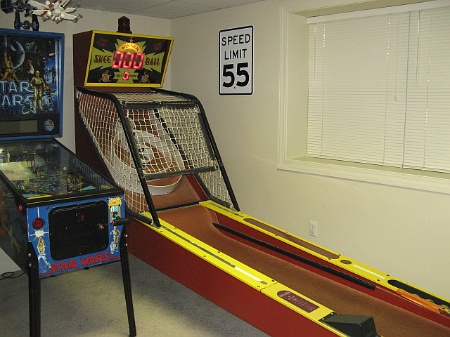
Using my wife’s interest as an excuse, many years ago I purchased a SkeeBall model H game. This 13 foot monster has resided in the corner of our basement ever since. Over the years we’ve played countless games on it as have a lot of guests. As I’ve progressed in my electronics hobby I started thinking about what it would take to replace the old control board from a pure how-do-you-do-that perspective and to also add some customized sounds and attract display just for fun. The Skeeball Controller presented here is the first generation of the control board that I have created.
What It Has To Do
In order to operate the game the controller has to :
-
Check the game start switch
-
Trigger the 120V solenoid that releases the balls for play
-
Check the lane switches for scores and balls going out of play
-
Play sounds when necessary via the existing 8 ohm speaker mounted in the game
-
Update the existing display comprised of 4 seven segment displays
-
Control the game lights comprised of 3 12v DC lamps around the score display and the 120V AC lamp on top
-
Keep up with game play and do all the above in a coherent manner
Gotta Have Tunes!
The biggest challenge of this project for me was getting a microcontroller to play music. I’ve never had to deal with generating anything analog, had no prior knowledge of sound/music to speak of nor have I ever had to deal with amplifiers other than plugging things into the back of a home stereo. What I did know is that I wanted this controller to play some nostalgic arcade tunes instead of the stock Skeeball ones. A little Google surfing, and AVRFreaks.net trolling lead me into some deep waters of sampling wav file and other things that will be cool to figure out, but seem over blown to generate the PacMan theme. I also didn’t want to have to deal with any data storage components which would be necessary to hold all that data. I then found some RTTTL ringtones of classic arcade games on this site : http://arcadetones.emuunlim.com/ . Check out Wikipedia for a great explanation of the format : http://en.wikipedia.org/wiki/Ring_Tone_Transfer_Language . So now I had a ready source of arcade tunes rendered down to what frequency/tone to generate and for how long.
Generating a signal to drive an amp/speaker was the next step. I’ll spare you the process as you can Google that just as easily as I can, but basically the common ways to do this are to use PWM (pulse width modulation) off of a single pin running at the given frequency, or you can use a R2R array of resistors to generate the signal sampling from a pre-sampled waveform pattern (in this case a sine wave). I chose the R2R method since I had the pins to spare and it also generated the purest waves for me on the oscilloscope.
My tunes are:
-
Game Start = PacMan theme
-
Score = last 4 notes of the Simpsons theme
-
Tickets/Winner = part of Super Mario World level cleared music from the SNES
-
Gutter ball = part of Street Fighter 2 stage music (sad/ominous)
-
End of Game = Funeral March
The Display
The existing display in the Skeeball game is comprised of 4 7-segment displays generated by small 12V lamps. The display has some driver circuitry built-in comprised of a series of 74c164 shift registers feeding uln2003a’s which in turn control the individual lamps. All of this plugs into the existing board via a 6 pin connector representing 12V and ground for the lamps, 5V and ground for the control along with separate data and clock lines to feed the data into the shift registers.
The biggest trick here is that those 74c164’s are CMOS level not TTL which means that they need a lot closer to 5V to register a high. To accomplish this a pull-up resistor had to be used. Don’t worry, if your interested you’ll see it on the schematic.
The Other Outputs
The other outputs are 2 120V AC outputs (solenoid and top light) and 3 12V DC lamps. The circuitry to drive the 2 120V outputs are the same as the one’s I used on my traffic light controller detailed on this site. It’s nothing more than using a pin to feed a opto-isolator (MOC3010) which in turn controls a triac (BTA10). The only difference in this application is the inclusion of an in-line fuse on the solenoid line just so it doesn’t burn up in case of a malfunction.
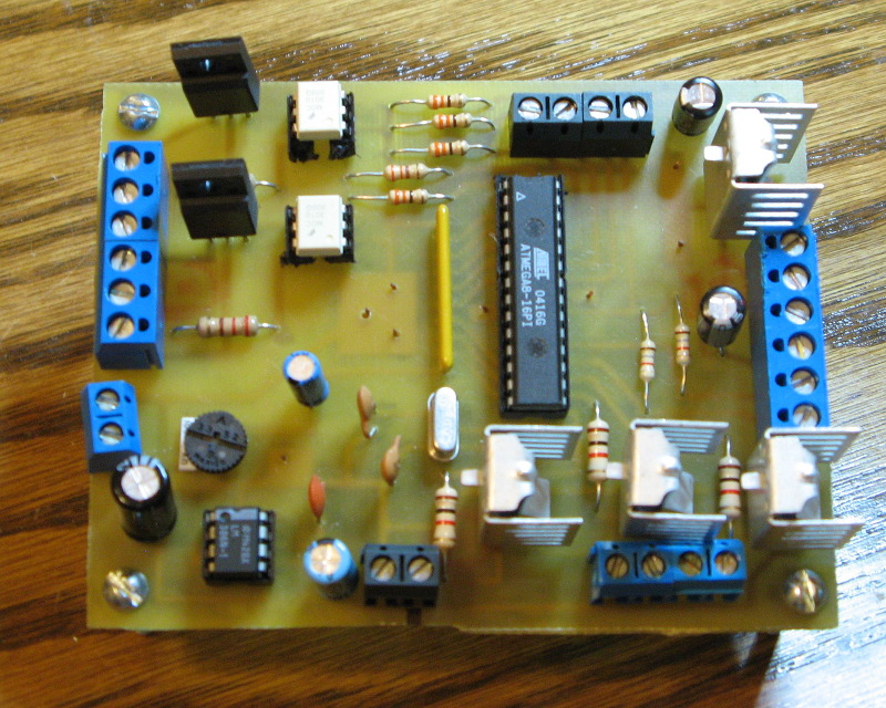
The three 12V lamps are driven by three TIP120 power transistors. In the board pictures below you’ll see them shrouded in clip-on heat sinks.
The Inputs
Inputs for the game are comprised of seven normally open contact switches. One for the start switch (I hot wired a start button on the front of the game long ago bypassing the coin mechanism). One switch lies in the ball out trough indicating when a ball is out of play. The other five switches lie behind each of the five scoring holes (10,20,30,40,50). All five scoring switches share a wire pair, so in order to tell what score you made on a ball we need to keep track of the number of pulses on the scoring line before the ball activates the ball out switch. The circuitry to pull this off is bread-and-butter stuff if you’ve ever messed with a microcontroller. The software is the fun part of this since it has to handle switch debouncing and keep track of all of the game logic.
The Circuit
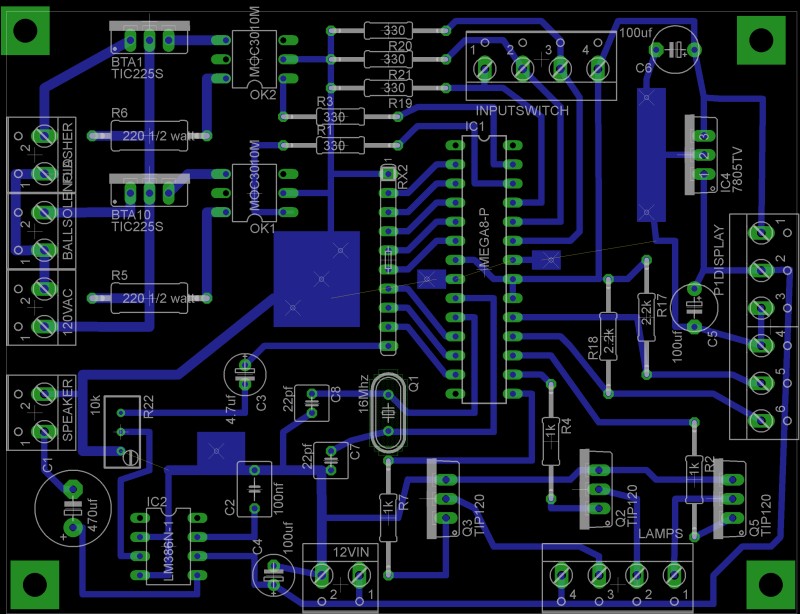
The heart of the board is an Atmel Atmega8 running on a 16Mhz external crystal. Everything else connects to the board via small screw terminals. Connected to the terminals are connector cables with Molex ends that mate to the existing system. I couldn’t find the appropriate type / gender of board mount Molex connectors to keep it all on the board . Maybe on the next version. The circuit and board were designed using Eagle by CadSoft. The circuit:
The Board
The following image is my current board design. I managed to keep it all on one layer (with only a few jumper wires, all of which are ground) since I wanted to be able to easily make the board at home. The top left side of the board is the high voltage side / 120V side. The bottom left is the audio amplifier using a LM386. Top right are the switch inputs and the 5V voltage regulator powered from a 12V wall-wart that powers the lamps in the display. The right side of the board is the connector to the existing score display. The bottom of the board is for the 12V power in and the header for the three 12V lamps we need to control. The entire board is 4″ by 3″, which I’m happy with considering the original board was 10 x 12. 🙂
And here’s the populated board prototype:
The Components
| Core Microcontroller Section / 5V Power | ||
| Qty | ID | Item |
| 1 | IC1 | Atmega8 |
| 1 | Q1 | 16Mhz crystal |
| 2 | C7,8 | 22pf capacitors for the crystal |
| 1 | IC4 | 7805 Voltage regulator |
| 2 | C5,6 | 100 uf electro-capacitors |
| Audio Out / Amp | ||
| 1 | RX2 | R2R resistor array in one package (Bourns 4610X-R2R-103LF) |
| 1 | R22 | 10k variable resistor (volume/gain) |
| 1 | C1 | 470uf electrolytic capacitor |
| 1 | C3 | 4.7uf electrolytic capacitor |
| 1 | C2 | 100nf capacitor |
| 1 | C4 | 100uf electrolytic capacitor |
| 1 | IC2 | LM386N power amp |
| 120V AC Control | ||
| 2 | BTA1,10 | BTA10 triacs |
| 2 | OK1,2 | MOC3010 opto-isolators |
| 2 | R5,6 | 220 ohm 1/2 watt resistors |
| 2 | R1,3 | 330 ohm 1/4 watt resistors |
| Switch Inputs | ||
| 3 | R19,20,21 | 330 ohm 1/4 watt resistors |
| Display Control | ||
| 2 | R17,18 | 2.2k ohm 1/4 watt resistors |
| Lamp Control | ||
| 3 | Q2,3,5 | TIP120 power transistors |
| 3 | R2,4,7 | 1k ohm 1/4 watt resistors |
| Connections | ||
| 9 | various | Screw terminals .. mix to fit |
The Program
This program started with the sound generation since it was going to be the most processor intensive part of the program. The tunes are stored in program code in two variable arrays. The first is RTTTLNote[x] which contains the note part in the highest four bits and the octave part in the lower four bits. RTTTLDuration[x] holds the duration data in the lower four bits and the duration modifier in the top four bits. (Read the RTTTL specification and you’ll understand what this means) There is also a RTTTLCount which represents the number of notes in the piece and RTTTLBPM which represents the beats-per-minute of the piece and is used to calculate note duration. The other key to sound generation is the 8 bit sampled sine wave stored in SineTable[x] . The entire program is built around a 31,250hz timer. Basically we step through the SineTable with a step sized based on the frequency we want for the given duration. We keep track of the duration through a global variable (MusicDelay) to let us know when that note needs to end and then look the next one up. So to play a tune we:
-
Call SetTune() to load the RTTTL info.
-
Call NextNote() to load the next step / duration info for the timer to process
-
Let the timer works it’s way through the SineTable to generate the frequency
-
Let the timer decrement the time keeper (MusicDelay) to let us know when to load the next note
-
MusicState and MusicPosition are global variable to keep track of if we are playing and if so which note count we are on
I know that sounds confusing, but chances are if you are still reading this then you are trying to implement something similar. Keep staring at it.
The rest of the code is all based around the 31,250hz timer, counter-timers and flags. Switch debounce is handled in code.
I’ve included comments in the code which should help try to make sense of it if you are interested. Here’s the current code: skeeball.c .
The Results
It works! Check out a video of the display on YouTube here : http://www.youtube.com/watch?v=T53lwfgze00 . It’s not perfect though. I have a hiss/crackle in my sound system now that seems to be tied to the lamp changes. For the next generation of this project I’m going to work with separate power supplies and/or a new power amp chip to try to fix the problem. Other than that it’s a fully functional replacement for the original control board with some customizations.
Next Generation
Now that I have a functional board the next step is to possibly add the following in the next generation:
-
Prettier sound – kill the hiss, add attack/decay to make the sounds smoother, add software volume control
-
More sound – ramp up to wav/mp3 files with external data storage.
-
Replace the existing rollover switches with no-contact IR beam switches.
-
Possibly replace the display with a LED matrix for better resolution/greater flexibility
-
Add some other game options like Follow the Leader or a 2 player Cricket (if you play darts you’ll understand)
If you have ideas or comments please let me know.


