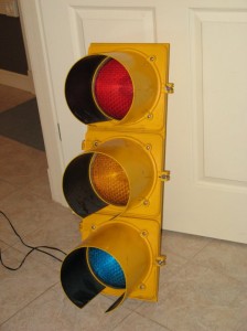
What gameroom would be complete without a real working traffic light? Well … probably all of them, but I wanted one anyway. I found this jewel on Ebay:
The next step was making it behave like a real traffic light with the proper sequence etc. I’ve been playing around with electronics and programming microcontrollers for a little while now, but making this light work correctly would be my first “useful” project.
The Goal
My goal was to have a traffic light controller board that would :
- Fit into the light housing
- Perform different light sequences (Standard, Flashing Red, Flashing Yellow)
- Not catch on fire
- Given me a reason to etch my first circuit board
The Circuit
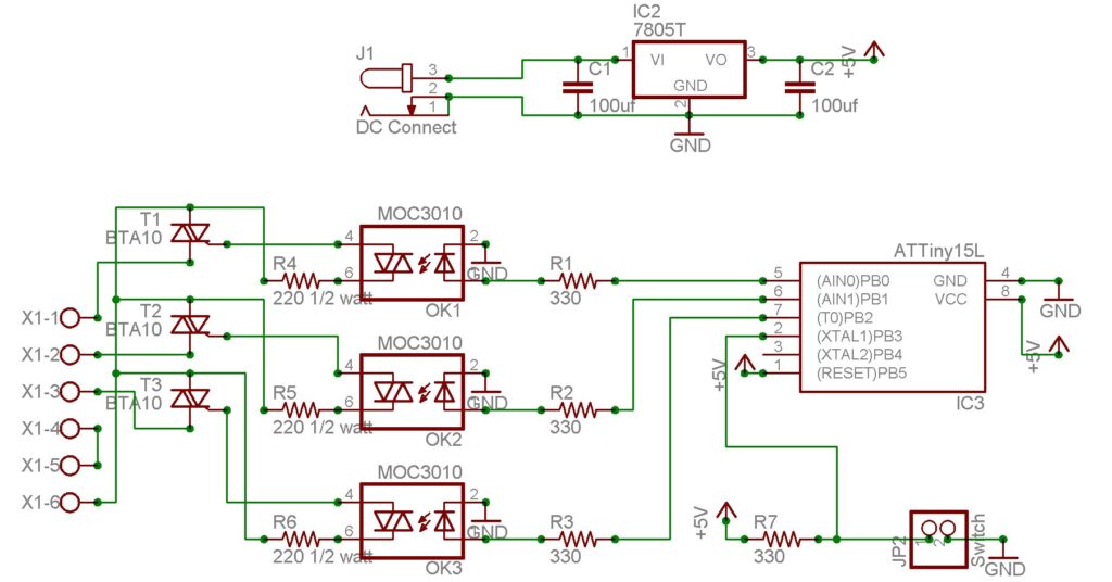
In order to save board size I chose the Atmel ATTiny15L microcontroller for the most bang for the buck in an 8 pin package. The only downside was that I was forced to program it in assembly language and I wasn’t able to use WinAVR as I normally do. So the basic components started out as the microcontroller, a voltage regulator (7805) to feed it and a push button to swap between light sequences. The outputs from the microcontroller go to three optoisolators (MOC3010) which in turn drive three triacs (BTA10) to feed power to the three lamps connected via a small screw terminal block. The finished circuit :
The Parts
Here are the parts used with their Jameco part numbers
| Qty | Item | Jameco Part# |
| 3 | BTA10 triacs | 657221PS |
| 3 | 220 ohm ½ watt resistors | various |
| 3 | MOC3010 opto-isolators | 698912 |
| 4 | 330 ohm ¼ watt resistors | various |
| 1 | ATTiny15L | 248196PS |
| 1 | 7805 Voltage regulator | 51262 |
| 2 | 100 uf electro-capacitors | 198969PS |
| 1 | DC Female Power Connector (2.1mm) | 137672 |
The Board
I designed the circuit using Eagle Layout Editor (http://www.cadsoftusa.com/). It measures 2″ x 4″ with four mounting holes to match the posts in the traffic light. The finished board with components looks like :
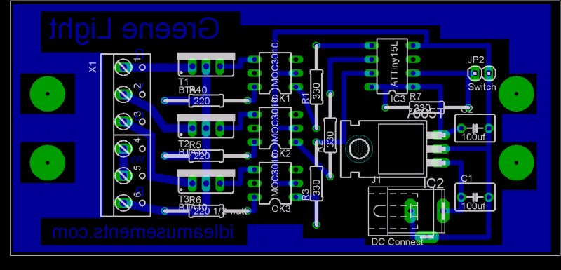
I used the laser printer / etch method as described on this site http://electrons.psychogenic.com/modules/arms/art/10/pcb_howto.php to produce the circuit board.
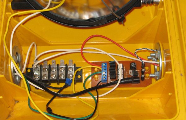
The finished board mounted in the light
The Code
The microcontroller is setup to interrupt itself every 164 milliseconds. On the interrupt it looks around to see if it needs to update the light pattern based on the variables of Tick (running count), State (which pattern we are on), Phase (which part of the pattern) and ChangeTicks (what tick we need to look for the next phase change on). The other thing that happens at interrupt is to check the status of the push button. After 2 successive button down polls we move on to the next light sequence / State. Anyway, here’s the code:
.include "C:Program FilesAtmelAVR ToolsAvrAssembler2Appnotestn15def.inc"

; PB0 (pin 5) = red Light
; PB1 (pin 6) = yellow Light
; PB2 (pin 7) = green Light
; PB4 (pin 2) = switch input

.def Temp =r16
.def State =r17 ; indicates which light pattern we are on
.def Phase = r18 ; indicates which part of the pattern we are on
.def Ticks =r19 ; used to keep track of clock ticks
.def ChangeTicks = r20 ; indicates on which tick we need to look for a phase change
.def ButtonTicks = r21 ; keeps track of the push button for switch de-bounce

.equ RedLamp = 0
.equ YellowLamp = 1
.equ GreenLamp = 2

.org $0000
    rjmp start    ; reset
.org OVF0addr	 ;  TIMER0 overflow
    rjmp click   ; jump to click

start:
	;----- Setup ports -------
	ldi Temp,0x07
	out DDRB,Temp ; Set Output pins
	cbi PortB,RedLamp
	cbi PortB,YellowLamp
	cbi PortB,GreenLamp

	;-------- Initial Values --------
	ldi State,0x01
	ldi Phase,0x01
	ldi Ticks,0x00
	ldi ChangeTicks,0x00
	ldi ButtonTicks,0x00

	; Setup Timer
	; Internal clock  = 1.6 mhz
	ldi Temp,5
	out TCCR0,Temp ; Timer clock = system clock / 1024

	ldi Temp,1<<TOV0
	out TIFR,Temp ; Clear TOV0/ clear pending interrupts
	ldi Temp,1<<TOIE0
	out TIMSK,Temp ; Enable Timer/Counter0 Overflow Interrupt

	sei ; enable global interupt
	rjmp loop

loop:
   rjmp loop      ; endless loop waiting for clock interrupts

click:
	sbis PinB,4
	rjmp ButtonDown
	ldi ButtonTicks,0x00
	inc Ticks
	cp  Ticks,ChangeTicks
	BRGE Change
	reti
ButtonDown:
	inc ButtonTicks
	cpi  ButtonTicks,0x02
	BREQ ButtonChange
	cpi ButtonTicks,0x03 ; no not let ButtonTicks overload if held down
	BRGE ButtonOverload
	inc Ticks
	cp  Ticks,ChangeTicks
	BRGE Change
	reti
ButtonOverload:
	ldi ButtonTicks,0x02 ; so will go to 3 on next button down and loop
	inc Ticks
	cp  Ticks,ChangeTicks
	BRGE Change
	reti
ButtonChange:
	inc State
	ldi Temp,0x04
	cpse State,Temp ; skip next if equal
	rjmp ButtonChange2
	ldi State,0x01
ButtonChange2:
	ldi Phase,0x01
	ldi Ticks,0x00
	ldi ChangeTicks,0x00
	rjmp Change
Change:
	; handles branching between the states
	cpi State,0x01
	BREQ StateNormal
	cpi State,0x02
	BREQ StateFlashRed
	cpi State,0x03
	BREQ StateFlashYellow
	rjmp StateNormal ;catchall

; 6 Ticks = 1 second  -- really it's .98304 seconds

StateNormal:
	cpi Phase,0x01
	BREQ StateNormal1
	cpi Phase,0x02
	BREQ StateNormal2
	cpi Phase,0x03
	BREQ StateNormal3
	rjmp StateNormal1 ;catchall
StateNormal1:
	sbi PortB,RedLamp
	cbi PortB,YellowLamp
	cbi PortB,GreenLamp
	ldi Ticks,0x00
	ldi Phase,0x02
	ldi ChangeTicks,36
	reti
StateNormal2:
	cbi PortB,RedLamp
	cbi PortB,YellowLamp
	sbi PortB,GreenLamp
	ldi Ticks,0x00
	ldi Phase,0x03
	ldi ChangeTicks,36
	reti
StateNormal3:
	cbi PortB,RedLamp
	sbi PortB,YellowLamp
	cbi PortB,GreenLamp
	ldi Ticks,0x00
	ldi Phase,0x01
	ldi ChangeTicks,12
	reti

StateFlashRed:
	cpi Phase,0x01
	BREQ StateFlashRed1
	cpi Phase,0x02
	BREQ StateFlashRed2
	rjmp StateFlashRed1 ;catchall
StateFlashRed1:
	sbi PortB,RedLamp
	cbi PortB,YellowLamp
	cbi PortB,GreenLamp
	ldi Ticks,0x00
	ldi Phase,0x02
	ldi ChangeTicks,3
	reti
StateFlashRed2:
	cbi PortB,RedLamp
	cbi PortB,YellowLamp
	cbi PortB,GreenLamp
	ldi Ticks,0x00
	ldi Phase,0x01
	ldi ChangeTicks,3
	reti

StateFlashYellow:
	cpi Phase,0x01
	BREQ StateFlashYellow1
	cpi Phase,0x02
	BREQ StateFlashYellow2
	rjmp StateFlashYellow1 ;catchall
StateFlashYellow1:
	cbi PortB,RedLamp
	sbi PortB,YellowLamp
	cbi PortB,GreenLamp
	ldi Ticks,0x00
	ldi Phase,0x02
	ldi ChangeTicks,3
	reti
StateFlashYellow2:
	cbi PortB,RedLamp
	cbi PortB,YellowLamp
	cbi PortB,GreenLamp
	ldi Ticks,0x00
	ldi Phase,0x01
	ldi ChangeTicks,3
	reti
The Results
It works great! I mounted a small push button on top of the light that allows me to swap between the standard green, yellow, red sequence to a rapid flashing red to a rapid flashing yellow pattern.